
Project Description
In this post, I will show how to setup an Arduino DUE for use with Iteadlib with a basic Nextion HMI.
This basic project will meet the following requirements
– MCU to change pages in response to Button release
– MCU to toggle LED on D13 on Button press/release
– MCU to update a status text on Nextion
– MCU to increment and update a number
– Nextion timer to evaluate and update status based on value
– Communication set to 115200 baud
Materials Used:
– an Iteaduino DUE (ARM Atmel ATSAM3X8E)
– a Basic Nextion 3.2″ NX4024T032_011
– included Nextion 4 wire Power/UART cable
– 4 straight pins from Male/Male 2.54mm header
– Iteadlib Arduino Nextion Library v0.90
– Nextion Editor v0.53
– Arduino IDE v1.8.0
Step 1
Download the Iteadlib Arduino Nextion Library
a) goto Iteadlib Arduino Nextion Library github page
> https://github.com/itead/ITEADLIB_Arduino_Nextion
b) click Clone or Download and select Download ZIP
> https://github.com/itead/ITEADLIB_Arduino_Nextion/archive/master.zip
c) Save to a location you’ll remember on your hard drive (for Next step)
Step 2
Install the Iteadlib Arduino Nextion Library
In the Arduino IDE
Sketch > Include Library > Add .ZIP Library
Select and Open the Library zip file from step 1c.
Be sure to READ the library readme.md file for directions
Step 3
Configure the Nextion Library for use with the DUE.
Iteadlib is preconfigured for the ATMega 2560
The DUE will use many of the same configurations, not all
so pay close attention to small changes as they are needed.
As the DUE has 4 serials we will configure for
– dbSerial enabled
– nexSerial to use our hardware serial Serial2
b) Edit NexConfig.h
locate the line
#define DEBUG_SERIAL_ENABLE
and ensure that it is not commented out,
then locate the line defining nexSerial
#define nexSerial Serial2
ensure it is Serial2 (pins D0/D1)
c) Edit NexHardware.cpp
locate the nexInit() function, here we configure the baudrate for Serial Monitor and Nextion.
We will use the Serial Monitor and set its baudrate high (no need to waste more MCU time than is needed),
then we will also need to configure for Nextion.
We have chosen 115200 baud in our requirements, so locate the lines
dbSerial.begin(9600);
nexSerial.begin(9600);
and change these to our 250000/115200 baud
dbSerial.begin(250000);
nexSerial.begin(115200);
Finally, Arduino’s AVR SoftwareSerial is not ARM compatible
d) Edit Nextion.h
locate the line
#include NexUpload.h
ensure it is commented out or removed from this include list
//#include NexUpload.h
e) In the library folder rename NexUpload files
– rename NexUpload.h to NexUpload.h.txt
– rename NexUpload.cpp to NexUpload.cpp.txt
The Nextion HMI
Step 4
Creating the HMI for the Basic 3.2″ Nexiton NX4024T032_011
Picture Resources
– 1 background 240×400, add as Picture resource #0
Font Resources
– 1 8×16 ASCII ZI Font
Two Pages, page0 and page1
Page 0 contains
– Two Button Components
– Three Text Components
– One Number Component
– One Timer Component
Page 1 contains
– One Button Component
a) Start the Nextion Editor v0.53
b) Create a New Project
c) Name project Tutorial and click Save
Next the Settings Dialog opens to the Device TAB
d) Select Basic
e) Select NX4024T032_011 Model and click OK
Nextion Editor opens ready for the Project to be made
Step 5
Adding our Picture Resource for Page 0 background
a) in the Picture Pane, click +
b) Select your 240×400 picture file and click Open
The selected picture is now added as Picture Resource 0
Step 6
Set the Page page0 background to Picture Resource 0
a) set the page0 attribute .sta value dropdown to image and press return
b) double click the attribute .pic value and select resource 0 and press return
In the Event Pane, Preinitialize Event add
bauds=115200
This will now match our MCU side baudrate of 115200 from step 3c
Step 7
Adding our 8×16 Font
a) In the Font Pane click +
b) select your 8×16 ZI Font file (*.zi) and click Open
The Selected ZI Font is now added as Font Resource 0
Step 8
Add Button Component b0 (size 30×100) position 0,0
a) click attribute .txt value, type Page 1, press return
in the Event Pane,
b) check Send Component ID checkbox in Touch Release Event
Step 9
Add Text Component t0 (size 60×30) Position 0,82
a) click attribute .txt value, type Read:, press return
Step 10
Add Text Component t2 (size 80×30) Position 142,82
a) click attribute .txt value, type Normal, press return
b) click attribute .objname value, type t2, press return
c) click attribute .bco value, type 65504, press return
Step 11
Add Timer Component tm0 (size 80×30) Position 142,82
a) click attribute .tim value, type 50, press return
b) In Timer Event Code, add
if(n0.val>50)
{
  n0.bco=63488
  t2.txt="Too Hot!"
}else
{
  n0.bco=2016
  t2.txt="Normal"
}
Step 12
Add Number Component n0 (size 45×30) Position 80,82
Step 13
Add Text Component t1 (size 140×30) Position 0,154
a) click attribute .txt_maxl value, type 20, press return
b) click attribute .txt value, type Arduino Control, press return
Step 14
Add Button Component b1 (size 100×30) position 0,220
a) click attribute .txt value, type D13 LED, press return
in the Event Pane,
b) check Send Component ID checkbox in Touch Press Event
c) check Send Component ID checkbox in Touch Release Event
Step 15
Add new Page page1
in the Page pane click Add icon
a) click attribute .bco value, type 0, press return
Step 16
Add Button Component b0 (size 100×30) position 0,0
a) click attribute .txt value, type Back, press return
in the Event Pane,
b) check Send Component ID checkbox in Touch Release Event
Step 17
Compile the Nextion HMI project to a TFT file
On the Nextion Toolbar,
a) Click Save
b) Click Compile (which creates the Tutorial.tft file)
c) Optionally click Debug to test your HMI
Step 18
Preparing your microSD card
a) ensure the microSD card is embedded compatible
(I have good success with Kingston Class 10 HC 8GB microSDs)
b) ensure the microSD is format under Windows as FAT32
c) ensure there are no *.tft files on the microSD card
Step 19
Install the TFT to the Nextion device
In the Nextion Editor File Menu
a) Click Open Build Folder
b) copy Tutorial.tft to your prepared embedded microSD card
c) Turn power to the Nextion off.
d) Insert the microSD card with Tutorial.tft into Nextion device
e) Turn power to the Nextion on
f) Wait for Nextion to begin uploading and complete uploading
When Nextion completes uploading and states success
g) Turn power to the Nextion off
h) Remove the microSD card from the Nextion device
i) Turn the power to the Nextion on
j) Wait a few moments to ensure all firmware upgrades complete
At this point the Tutorial HMI should be running on the Nextion
The DUE MCU side of the Tutorial Project
Step 20
Include the Iteadlib Arduino Nexiton Library with the line
#include "Nextion.h"
Step 21
Declare essential MCU side HMI Components
– essential are the 2 pages, 3 Buttons, the n0 Number, and t1 Text
NexPage p0 = NexPage(0,0,"page0");
NexButton p0_b0 = NexButton(0,1,"b0");
NexNumber p0_n0 = NexNumber(0,5,"n0");
NexText p0_t1 = NexText(0,6,"t1");
NexButton p0_b1 = NexButton(0,7,"b1");
NexPage p1 = NexPage(1,0,"page1");
NexButton p1_b0 = NexButton(1,1,"b0");
Step 22
Build the nex_listen_list that the DUE will listen for
– only the buttons contained checked Send Component IDs
NexTouch *nex_listen_list[] = {
  &p0_b0, &p0_b1, &p1_b0, NULL
};
Step 23
Declare other MCU side Variables
– uint32_t myInt used for updating number n0
– uint32_t next used for when to trigger intermittent function
– #define ledPin 13 used to identify LED pin D13
uint32_t next, myInt = 0;
#define ledPin 13
Step 24
Write a function for each Send Component ID checked
– page0.b1 Press to turn LED on
– page0.b1 Release to turn LED off
– page0.b0 Release to change page to page 1
– page1.b0 Release to change page to page 0
void p0_b1_Press(void *ptr) {
  digitalWrite(ledPin, HIGH);
}

void p0_b1_Release(void *ptr) {
  digitalWrite(ledPin, LOW);
}

void p0_b0_Release(void *ptr) {
  p1.show();
}

void p1_b0_Release(void *ptr) {
  p0.show();
}
Step 25
Write the intermittent function for updating n0
– here we increment myInt from 0 to 100 and then circle back to 0
– and we update Nextion’s page0 n0 with the new value
void do_every_so_often() {
  myInt = (myInt + 1) % 101;
  p0_n0.setValue(myInt);
}
Step 26
Creating the setup() function
– first, initialize the Nextion with nexInit()
– setup and initialize the pin for the LED
– add in our four Press/Release functions
– set page0 t1 Text
– initialize our next value for our intermittent function
void setup() {
  nexInit();
  pinMode(ledPin,OUTPUT);
  digitalWrite(ledPin,LOW);
  p0_b0.attachPop(p0_b0_Release, &p0_b0);
  p0_b1.attachPush(p0_b1_Press, &p0_b1);
  p0_b1.attachPop(p0_b1_Release, &p0_b1);
  p1_b0.attachPop(p1_b0_Release, &p1_b0);
  p0_t1.setText("Arduino Text");
  next = millis();
}
Step 27
Create our loop() code
– the first line is nexLoop()
– the next is a conditional and bridled intermittent call
void loop() {
  nexLoop(nex_listen_list);
  if(millis() >= next) {
    next = millis()+500;
    do_every_so_often();
  }
}
Step 28
In the Arduino IDE, compile the code to ensure there are no coding issues.
#include "Nextion.h"

NexPage p0 = NexPage(0,0,"page0");
NexButton p0_b0 = NexButton(0,1,"b0");
NexNumber p0_n0 = NexNumber(0,5,"n0");
NexText p0_t1 = NexText(0,6,"t1");
NexButton p0_b1 = NexButton(0,7,"b1");
NexPage p1 = NexPage(1,0,"page1");
NexButton p1_b0 = NexButton(1,1,"b0");

NexTouch *nex_listen_list[] = {
  &p0_b0, &p0_b1, &p1_b0, NULL
};

uint32_t next, myInt = 0;
#define ledPin 13

void p0_b1_Press(void *ptr) {
  digitalWrite(ledPin, HIGH);
}

void p0_b1_Release(void *ptr) {
  digitalWrite(ledPin, LOW);
}

void p0_b0_Release(void *ptr) {
  p1.show();
}

void p1_b0_Release(void *ptr) {
p0.show();
}

void do_every_so_often() {
  myInt = (myInt + 1) % 101;
  p0_n0.setValue(myInt);
}

void setup() {
  nexInit();
  pinMode(ledPin,OUTPUT);
  digitalWrite(ledPin,LOW);
  p0_b0.attachPop(p0_b0_Release, &p0_b0);
  p0_b1.attachPush(p0_b1_Press, &p0_b1);
  p0_b1.attachPop(p0_b1_Release, &p0_b1);
  p1_b0.attachPop(p1_b0_Release, &p1_b0);
  p0_t1.setText("Arduino Text");
  next = millis();
}

void loop() {
  nexLoop(nex_listen_list);
  if(millis() >= next) {
    next = millis()+500;
    do_every_so_often();
  }
}
Step 29
Upload the sketch to the DUE
Step 30
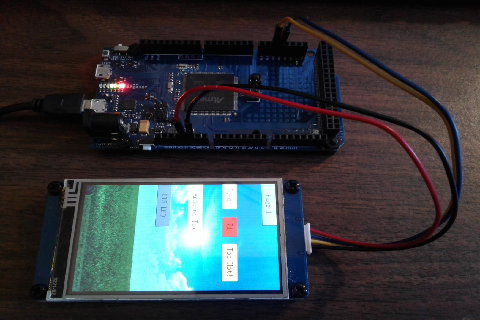
For each of the 4 Nextion DuPont connector ends
– Insert a header pin into the end so can now be plugged in directly to the DUE
Nextion RX (yellow) connected to DUE Serial2 TX2
Nextion TX (blue) connected to DUE Serial2 RX2
Nextion GND (black) connected to DUE GND
Nextion 5V (red) connected to DUE 5V
Power Note:
I can connect this 3.2″ Nextion into this DUE Board because:
1) I confirmed with the board and this Nextion model’s Datasheets
as such, this board will deliver the recommended current.
2) Do not connect direct UNLESS you also make a similar confirmations
(for your specific board and your model Nextion) via Datasheets.
Nextion Datasheets are clear on the recommended supply it asks for.
Conclusion
We have now successfully created a basic HMI for Nextion
using a DUE MCU and the Iteadlib Arduino Nextion Library.
Nextion Button page0 b0
– notifies the DUE, the DUE changes page to page 1
Nextion Button page1 b0
– notifies the DUE, the DUE changes page to page 0
Nextion Button page 0 b1 press
– notifies the DUE, and LED is lit while pressed
Nextion Button page 0 b1 release
– notifies the DUE, and LED turns off when released
the DUE updates page0 t1 to “Arduino Text” from setup
In loop, periodic conditional and bridled
– update MCU side myInt and updates page0 n0
Nextion side timer code evaluates n0
– updates n0 background and t2.txt based on value